- 您现在的位置:买卖IC网 > Sheet目录987 > LD4T06P0 (Red Lion Controls)TIMER 6 DIGIT 4.0" 120VAC RED
�� �
�
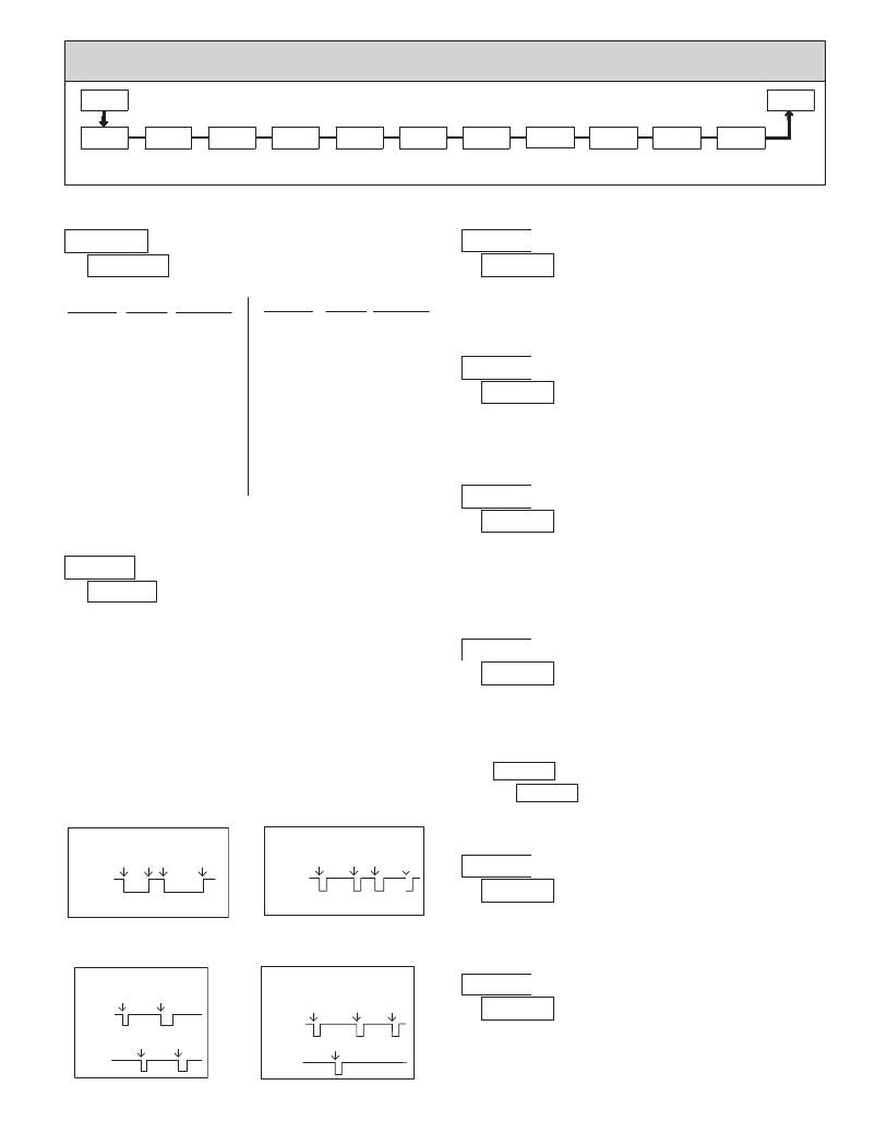
�5.1� MODULE� 1� -� T� IMER� I� NPUT� P� ARAMETERS� (� ?????� )�
�1-INP�
�PAR�
�PARAMETER� MENU�
�Pro�
�rAN6E�
�Timer�
�Range�
�INP OP�
�Timer� Input�
�Operation�
�FILtEr�
�Timer� Input�
�Filter�
�t-dir�
�Timing�
�Direction�
�t-Strt�
�Timer� Start�
�Value�
�t-StOP�
�Timer� Stop�
�Value�
�FLASH�
�Flash� Timer�
�Run� Indicator�
�t P-UP�
�Timer� Run�
�State� At�
�r P-UP�
�Timer� Reset�
�At� Power-up�
�USrINP�
�User� Input�
�Function�
�USrASN�
�User� Input�
�Assignment�
�Power-up�
�TIMER� RANGE�
�TIMER� INPUT� FILTER�
�?????� ?�
�?� ??????�
�18� TIMER� RANGE� SELECTIONS�
�(� ??� =� SEC;� ??� =� MIN;� ?� ??� =� HR;� ?� ??� =� DAY� )� ?�
�??????� ?�
�?� ??�
�??�
�???�
�Provides� a� 50� msec� software� debounce� for� the� Timer� Inputs� (A� and� B).� Select�
�RANGE�
�SELECTION�
�MAXIMUM�
�DISPLAY�
�DISPLAY�
�RESOLUTION�
�RANGE�
�SELECTION�
�MAXIMUM�
�DISPLAY�
�DISPLAY�
�RESOLUTION�
�??� when� using� relays� or� switch� contacts� as� a� signal� source.�
�?�
�SECONDS�
�??????�
�???????�
�???????�
�???????�
�MINUTES�
�??????�
�???????�
�???????�
�HOURS�
�??????�
�???????�
�???????�
�??????�
�???????�
�???????�
�???????�
�??????�
�???????�
�???????�
�??????�
�???????�
�???????�
�1� SEC�
�0.1� SEC�
�0.01� SEC�
�0.001� SEC�
�1� MIN�
�0.1� MIN�
�0.01� MIN�
�1� HR�
�0.1� HR�
�0.01� HR�
�MINUTES/SECONDS�
�???????� ???????�
�????????� ????????�
�????????� ????????�
�HOURS/MINUTES�
�???????� ???????�
�????????� ????????�
�????????� ????????�
�HOURS/MINUTES/SECONDS�
�????????�
�????????�
�DAYS/HOURS/MINUTES�
�????????� ????????�
�1� SEC�
�0.1� SEC�
�0.01� SEC�
�1� MIN�
�0.1� MIN�
�0.01� MIN�
�1� SEC�
�1� MIN�
�TIMING� DIRECTION�
�?????� ?�
�??� ??�
�??�
�Bi-directional� timing� capability.� Select� the� timing� direction� desired� for� the�
�application.�
�TIMER� START� VALUE�
�??????� ?�
�??????� to� ??????�
�?� ??????�
�TIMER� INPUT� OPERATION�
�The� Timer� returns� to� this� value� whenever� a� Timer� Reset� occurs.� The� value� is�
�???� ?� ??� ?�
�?� ?????�
�?????� ??????�
�??????� ??????�
�??????�
�??????�
�??????�
�??????�
�entered� in� the� same� display� format� as� the� Timer� Range� selected.� Non-zero�
�values� are� normally� used� for� “timing� down”� applications,� but� they� can� also�
�provide� an� offset� value� when� timing� up.�
�This� parameter� determines� how� the� Timer� Input� Signals� affect� the� Run/Stop�
�status� of� the� Timer.� Timing� diagrams� are� shown� below� for� level� active� and� edge�
�triggered� (1-input� or� 2-input)� operation.� For� single� input� modes� (Input� A� only),�
�Input� B� provides� a� level� active� Timer� Inhibit� function.� In� the� Display� Hold�
�mode,� the� timer� display� value� remains� held� and� only� updates� when� a� Timer�
�??????� ?�
�?� ??�
�TIMER� STOP� VALUE�
�??� ???�
�?????� ?�
�Start (Input A) or Timer Stop (Input B) edge occurs.�
�The� timer� reset� (� ???� )� operating� modes� are� identical� to� the� other� modes� in� the�
�diagrams,� except� the� timer� display� value� is� reset� at� the� Time� Start� edges.�
�The� Timer� can� also� be� stopped� at� a� Timer� Stop� Value� or� at� Setpoint� output�
�activation� or� deactivation.� This� type� of� Stop� condition� is� cleared� when� a� Timer�
�Reset� occurs,� or� another� start� edge� is� applied� on� the� timer� input.�
�For� Reset� Modes� (� ???� ),� the� timer� is� reset� at� Time� Start� edge.�
�The� Timer� stops� when� this� value� is� reached� regardless� of� the� signal� levels� on�
�the� timer� inputs.� Selecting� ???� displays� a� sub-menu� where� the� Stop� Value� is�
�entered� in� the� same� display� format� as� the� Timer� Range� selected.� This� stop�
�condition� is� cleared� when� a� Timer� Reset� occurs� or� another� start� edge� is� applied�
�on� the� timer� input.� Select� ??� if� a� Stop� Value� is� not� desired.�
�??????� to� ??????�
�?� ??????�
�?????� ,� ???????�
�??????� ,� ??????�
�Level� Active� (Gated)� Operation�
�Edge� Triggered� Operation� -1� Input�
�FLASH� TIMER� RUN� INDICATOR�
�INPUT� A�
�Time�
�Start�
�Time� Time�
�Stop� Start�
�Time�
�Stop�
�INPUT� A�
�Time�
�Start�
�Time�
�Stop�
�Time�
�Start�
�Time�
�Stop�
�?????� ?�
�?� ???�
�??�
�???�
�INPUT� B� -� Timer� Inhibit� (Level� Active)�
�??????� ,� ??????�
�INPUT� B� -� Timer� Inhibit� (Level� Active)�
�??????� ,� ??????�
�Select� ???� to� have� the� Timer� Run� indicator� flash� when� the� timer� is� running.�
�TIMER� RUN� STATE� AT� POWER-UP�
�Edge� Triggered� Operation� -� 2� Input�
�Time� Time�
�Start� Start�
�INPUT� A�
�Edge� Triggered� Operation� -� 2� Input,�
�with� Display� Hold�
�Time� Start,� Time� Start,� Display�
�Display� Update� Display� Update� Update�
�?� ?� ????� ?�
�?� ????�
�????�
�????�
�INPUT� A�
�Determines� the� Run/Stop� state� of� the� Timer� at� Power-up.� This� parameter�
�INPUT� B�
�Time�
�Stop�
�Time�
�Stop�
�INPUT� B�
�Time� Stop,�
�Display� Update�
�does� not� apply� to� ?????� Input� Operation.�
�????� -� Timer� Stopped� at� power-up,� regardless� of� prior� Run/Stop� state�
�????� -� Timer� assumes� the� Run/Stop� state� it� was� in� prior� to� power-down�
�7�
�发布紧急采购,3分钟左右您将得到回复。
相关PDF资料
LFSTBEB7361
BOARD DEV ACCELEROMETER MMA7361L
LFSTBEB7455
BOARD DEV ACCELEROMETER MMA7455L
LFSTBEB8450
BOARD DEV ACCELEROMETER MMA8450
LFSTBEB845X
EVAL BOARD FOR MMA845XQ
LH1518AT
RELAY SSR SPST 250V 300MA 6DIP
LI12-1A79
RELAY REED SPST 1A 12V
LK1AF-24V
RELAY GEN PURPOSE SPST 5A 24V
LKG1AF-24V-16-1
RELAY GEN PURPOSE SPST 16A 24V
相关代理商/技术参数
LD50
制造商:General Tools 功能描述:Deluxe Lightning Detector 制造商:General Tools 功能描述:DETECTOR LIGHTNING
LD-50
制造商:API TECHNOLOGIES 功能描述: 制造商:API Technologies Corp 功能描述:
LD5000
制造商:WTE 制造商全称:Won-Top Electronics 功能描述:50A 10mm LUCAS TYPE PRESS-FIT DIODE
LD5001
制造商:WTE 制造商全称:Won-Top Electronics 功能描述:50A 10mm LUCAS TYPE PRESS-FIT DIODE
LD5002
制造商:WTE 制造商全称:Won-Top Electronics 功能描述:50A 10mm LUCAS TYPE PRESS-FIT DIODE
LD5003
制造商:WTE 制造商全称:Won-Top Electronics 功能描述:50A 10mm LUCAS TYPE PRESS-FIT DIODE
LD5004
制造商:WTE 制造商全称:Won-Top Electronics 功能描述:50A 10mm LUCAS TYPE PRESS-FIT DIODE
LD5005
制造商:WTE 制造商全称:Won-Top Electronics 功能描述:50A 10mm LUCAS TYPE PRESS-FIT DIODE